Context
This project represents my bachelor’s thesis. The starting point of the project was the electromagnetic design of a transverse flux motor, which had been carried out at the Technical University of Berlin. This design stands out for having a magnetic field in which the field lines follow a three-dimensional trajectory. Electric motors commonly used in industry use laminations to direct the magnetic field perpendicular to the axis. In this motor, the magnetic field is directed through iron wires, thus creating the trajectory shown in the following image. Based on the electromagnetic design shown in the image, the mechanical design of the motor and the necessary tools for its manufacturing were developed.
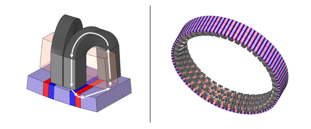
In his dissertation, P. Seibold developed a transverse flux motor, which can be considered a predecessor design to the one used in this project. P. Seibold uses a laminated steel package system, which directs the magnetic field along a trajectory similar to the one shown in the image. However, if the laminated steel system is replaced with iron wires, which are molded into the desired shape, the losses due to remagnetization are significantly reduced. This concept is described in more detail in the article “Optimization of magnetic flux paths in transverse flux machines through the use of iron wire wound materials“.
Motor design
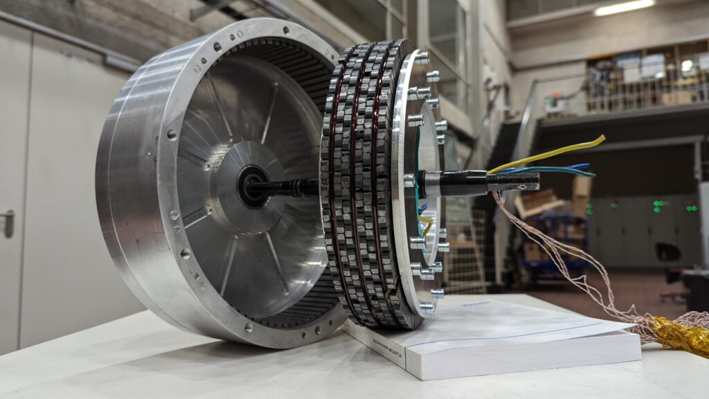
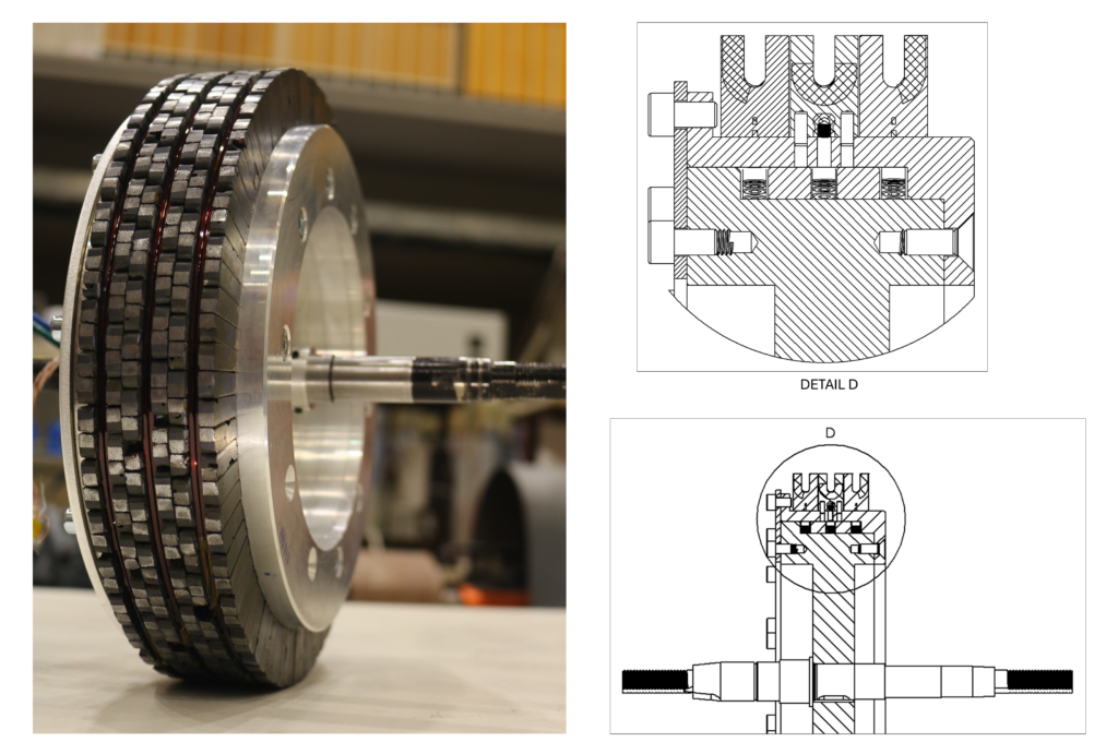
The motor presented here is an external rotor motor. It is a three-phase synchronous motor with 90 poles. It has three coils, each connected to one of the three phases. The rotor has 270 permanent magnets. Between each magnet are two cuboid iron pieces, which direct the magnetic field. The stator uses 270 pieces made of iron wires, which wrap around the three coils and shape their magnetic field. The motor’s shaft was recycled from an electric motorcycle. The bearings were replaced with three ball bearings, which are secured to the shaft with retaining rings and to the rotor through a press fit.
The air gap between the rotor and the stator has a nominal size of 0.4 mm. This measurement was part of the electromagnetic design, which was carried out before beginning the thesis. Therefore it was considered a requirement to be met. A reduction in the air gap would enhance the electromechanical characteristics of the motor. However, an increase in this spacing would significantly reduce power and efficiency. In the area near the coils, the motor’s temperature increases noticeably when the three-phase current is applied. This temperature rise leads to an expansion of the stator material, thereby reducing the size of the air gap. Therefore, highly precise tolerances in both the rotor and stator are required, and the materials near the coil must possess a low coefficient of thermal expansion.
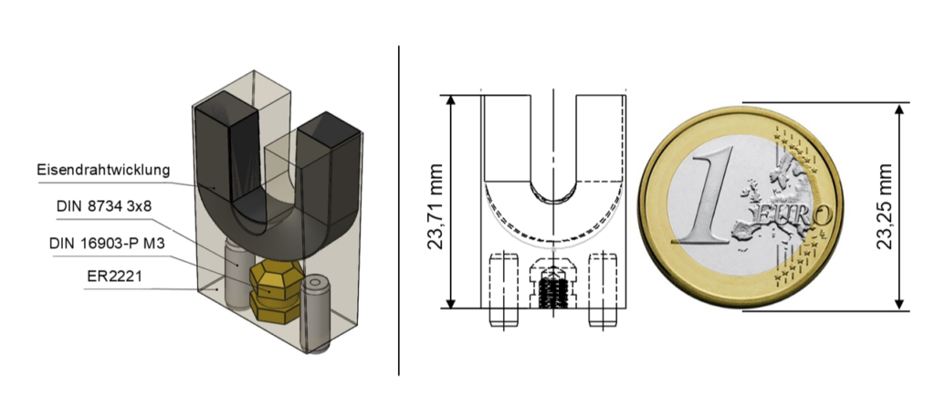
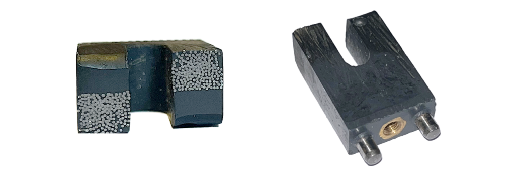
The magnetic flux guide elements in the stator must meet the strict tolerances and be capable of withstanding periodic tangential and radial forces of up to 66.5 N. The proposed solution involved the independent encapsulation of each magnetic flux guide element of the stator in epoxy resin. The ER2221 epoxy resin from the manufacturer Electrolube was chosen due to its high tensile strength (50 N/mm²), excellent thermal resistance (150 °C), low coefficient of thermal expansion (30 ⋅ 10⁻⁶ K⁻¹), and high thermal conductivity (1.20 W/mK). For attachment to the stator, a threaded insert was also encapsulated in each piece. Additionally, two alignment pins were incorporated into each component to ensure precise positioning. The following image illustrates the design of the component.
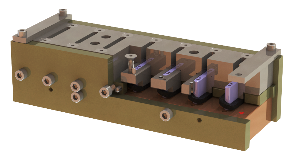
Initially, the use of a solid ring for the stator was considered. However, this design would not allow for the screwing of the encapsulated threaded inserts. Therefore, the stator ring was divided into four separate rings. The outer ring contains perforations to facilitate the mounting of the external components. The creation of three recesses on the inner diameter posed a manufacturing challenge. To address this, two intermediate rings were designed to provide structural reinforcement to the outer ring. Finally, the inner ring connects the outer rings to the shaft. The following image illustrates the stator design.
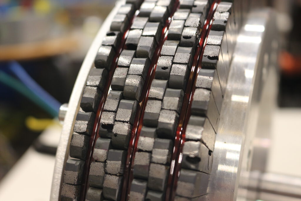
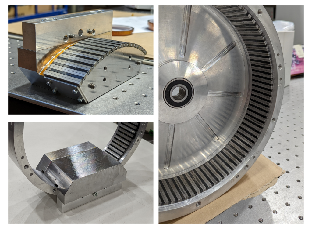
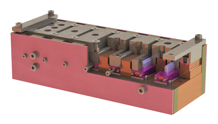
The rotor consists of magnets, cuboid-shaped iron pieces, an outer ring, and two side covers that connect the outer ring to the bearings. Similar to the stator, the rotor components must adhere to strict radial and tangential tolerances. If the pieces were simply assembled sequentially, the cumulative tolerances of the 270 consecutive elements would result in significant inaccuracy. To address this, a specialized assembly tool was developed to evenly distribute tangential inaccuracies around the rotor’s perimeter and ensure compliance with the radial tolerance.
The tool utilizes the magnetic force generated by the magnets. It is made of a ferromagnetic material, allowing the components to adhere to its surface. The tool is bolted to the motor using alignment pins to ensure precise positioning. The following image illustrates the process of gluing the magnets to the rotor ring.
Manufacturing of the Magnetic Flux Guide Elements
The manufacturing process for the magnetic flux guide elements of the stator is divided into six steps:
- Winding of the iron wire
- Annealing in a furnace to reduce internal material stresses
- Bending and pressing of the winding to achieve the required three-dimensional shape
- Annealing in a furnace to reduce internal material stresses
- Molding in epoxy resin
- Final cutting and machining of the components
The first step in the manufacturing process involves winding the iron wire into a coil. This was carried out using a winding machine. For this purpose, the winding core shown in the following image was developed, which allowed the wire to be shaped into the desired form. The core was made of stainless steel, enabling subsequent annealing.
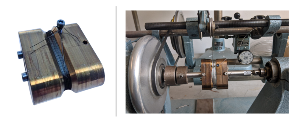
After the wire is wound, it is annealed within the same core. This is necessary because the wire experiences mechanical stresses, which hinder subsequent manufacturing processes. Annealing helps to reduce the internal stresses of the material, preventing the winding from deforming when this is separated from the components that hold it in place.
After the wires are wound and annealed, they are inserted into a second tool that shapes them into the desired three-dimensional form. This tool compresses the wires and ensures the strict tolerances are met in the area near the air gap. This deformation introduces new internal stresses in the material, which deteriorates its magnetic properties. For this reason, after the wires are pressed, they are annealed once again to reduce the material’s stresses.
Next, the wires are inserted into a third tool, which allows for encapsulation in epoxy resin. After pouring the liquid resin, a vacuum is generated. The air, which is trapped between the wires, escapes in the form of bubbles. After the resin has remained under vacuum for a few minutes, air is introduced, restoring atmospheric pressure. This process ensures that the resin envelops all the wires, including those deeper in the winding core. The alignment pins and threaded inserts are positioned at the corresponding places in the tool and, after the resin has cured, are firmly integrated into the component.
Once the epoxy resin solidifies, the parts are removed from the tool. Finally, the excess resin is removed, the component is cut in half, and the cut surfaces are machined to ensure compliance with radial tolerances. The following image shows the resulting component.
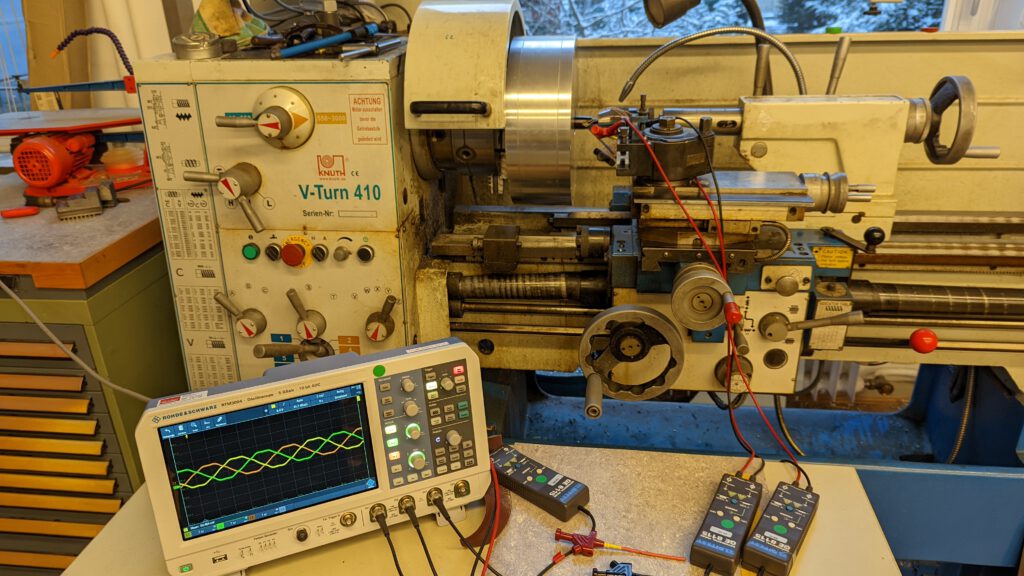
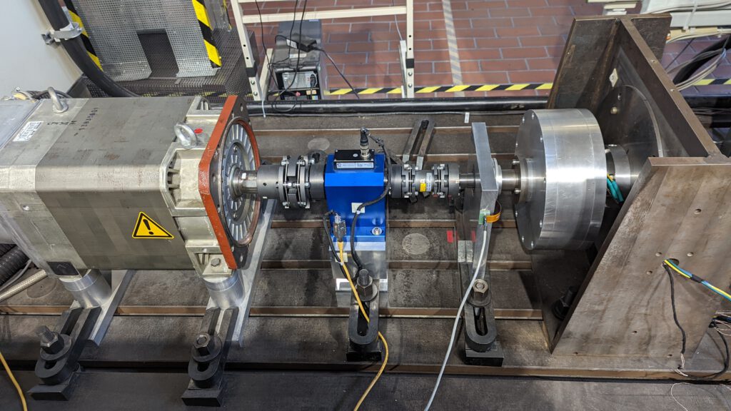
Commissioning
After the completion of my thesis, the motor was commissioned, and its proper operation was verified at the Technical University of Berlin.